Introduction:
The NSX-T VLAN Based OneArm Load Balancer on a Standalone Tier-1 Gateway scenario is often of interest to VMware customers that use NSX-T without VXLAN. These customers primarily use NSX-T for micro-segmentation and edge functionality.
Network Topology:
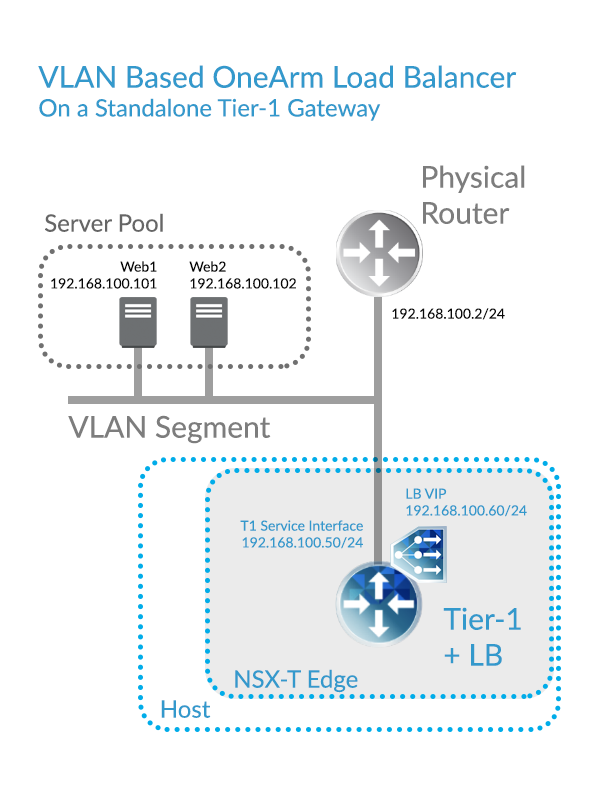
In this article, we will look at a simple base topology from which you can build. Although it’s not a requirement for this topology, Server Pool Members, the T1 Service Interface, and the LB VIP will all be on the same IP Subnet. With all of these IPs collapsed down to a single subnet, routing is simplified.
Some notes on this topology:
- The Load Balancer is deployed on a Tier-1 Gateway, the Load Balancer is not available on a Tier-0 Gateway
- The Tier-1 Gateway is deployed on an NSX-T Edge Cluster
- The Tier-1 Gateway is Standalone, meaning that it doesn’t connect to another Tier-0 or Tier-1 Gateway
- The Standalone Tier-1 Gateway can have multiple Service Interfaces, but in that case, Load Balancing is not supported.
- The NSX-T edge can be an Edge Appliance or a Bare Metal Edge
- The Server Pool workloads are VLAN backed, not NSX-T Overlay backed
The following Topology diagram illustrates that the Load Balancer resides on an Tier-1 Gateway, and that the Tier-1 Gateway resides on an NSX-T Edge.
Important Caveat with this Scenario:
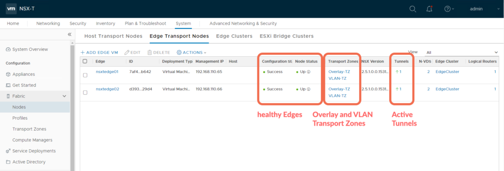
Even if no overlay is used (everything is VLAN based), the Edge Node needs to be provisioned for both Overlay and VLAN Transport Zones.
This is because the Edge requires at least one GENEVE tunnel up to get it’s LB hosted Standalone T1 Active.
If this Edge is dedicated to hosting only this Standalone Tier-1 Gateway, then the GENEVE tunnel would be between the HA Active Edge TEP and the HA Standby Edge TEP.
Let’s look at the detailed steps required to deploy a VLAN Based OneArm Load Balancer on a Standalone Tier-1 Gateway.
Step 1: Verifying Edge Status
The Tier-1 Gateway needs to be instantiated on an Edge Cluster, let’s begin by verifying it is healthy, with at least one active tunnel, and provisioned for both Overlay and VLAN Transport Zones.
Step 2: Create a Segment on the VLAN Transport Zone
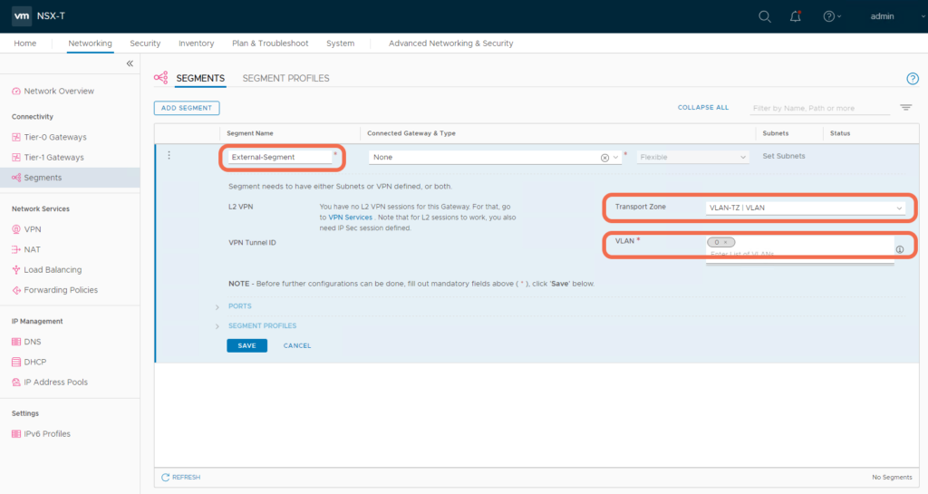
In my lab, this is VLAN 0. Be sure to specify the VLAN where the Tier-1 Gateway Service Interface will connect.
Step 3: Create a Tier-1 Gateway
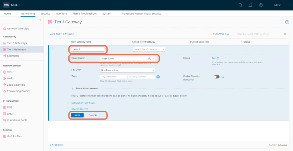
Instantiate the Tier-1 Gateway on an Edge Cluster. You need to specify an Edge Cluster since this Tier-1 Gateway will host load balancer stateful services.
Step 4: Add a Tier-1 Gateway Service Interface
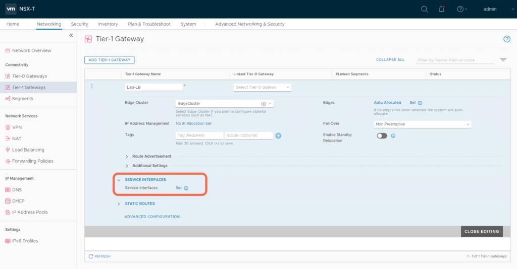
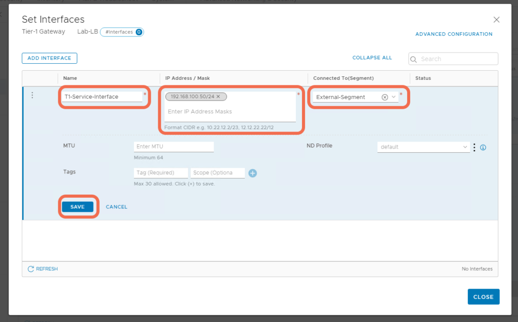
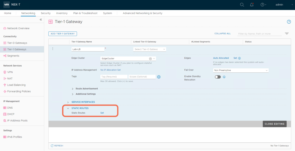
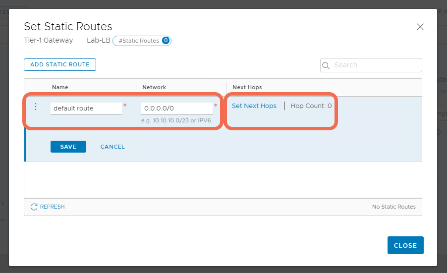
Step 5: Add a Default Static Route to the Tier-1 Gateway
Specify a default quad 0 route where the next hop is the physical router interface.

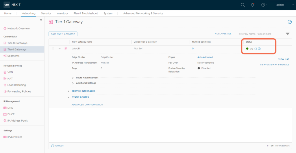
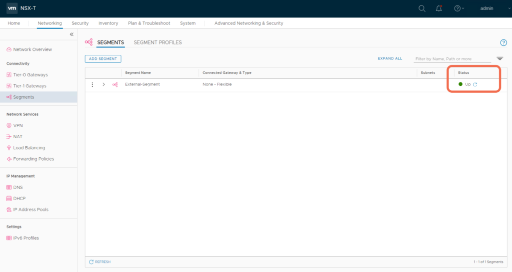
Step 6: Verify Gateway and Segment Status are Up
After the configurations are realized, verify they appear up and healthy.
Step 7: Verify the Tier-1 Gateway Service Interface is reachable
At this point, the Tier-1 Gateway Service Interface should be reachable from the physical environment. If it is not, it’s time for some NSX-T Edge troubleshooting: https://spillthensxt.com/configuring-nsx-t-edge-connectivity-to-physical/
# ping 192.168.100.50
PING 192.168.100.50 (192.168.100.50) 56(84) bytes of data.
64 bytes from 192.168.100.50: icmp_seq=1 ttl=63 time=10.6 ms
64 bytes from 192.168.100.50: icmp_seq=2 ttl=63 time=5.48 ms
64 bytes from 192.168.100.50: icmp_seq=3 ttl=63 time=3.90 ms
Step 8: Add a Load Balancer to the Tier-1 Gateway
Add a Load Balancer and specify the hosting Tier-1 Gateway.
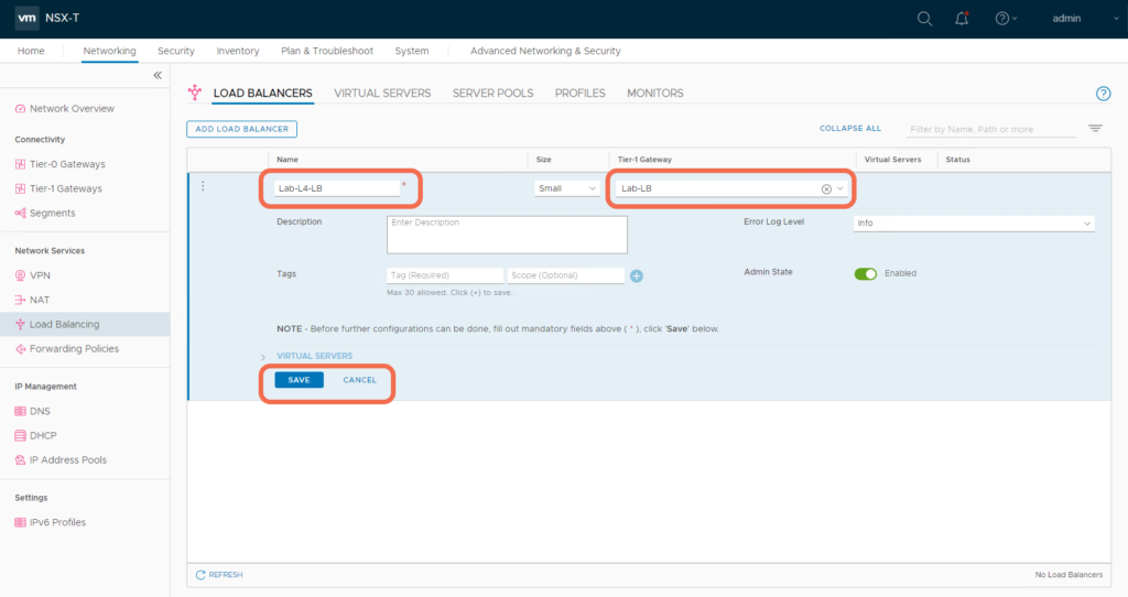
Specify a Virtual Server.

Create a Server Pool.
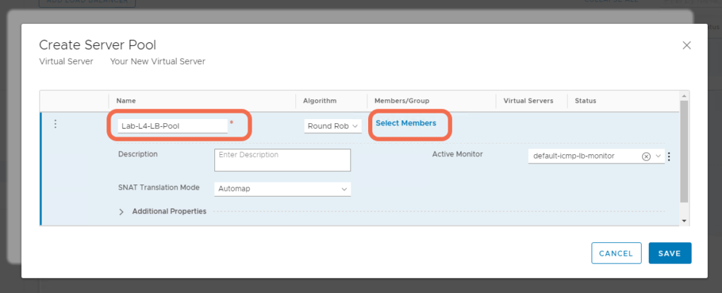
Add Pool Members.
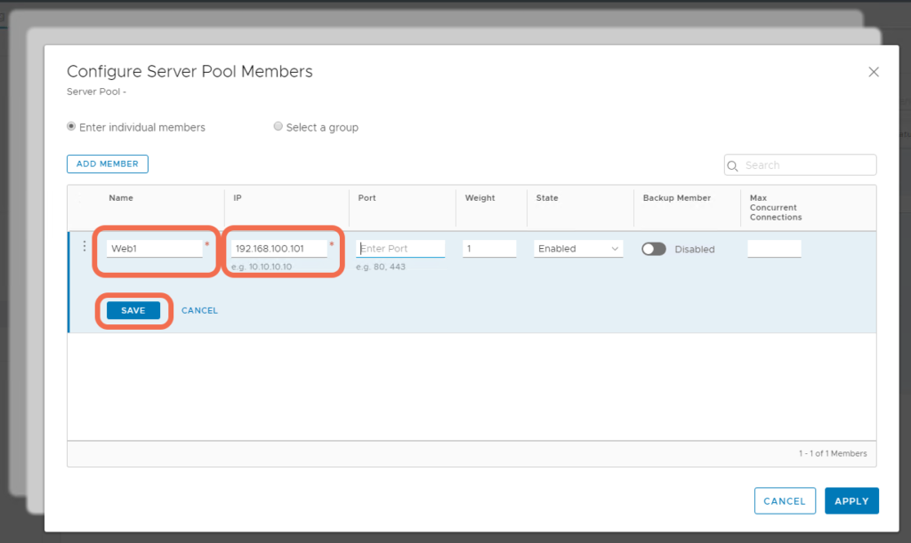
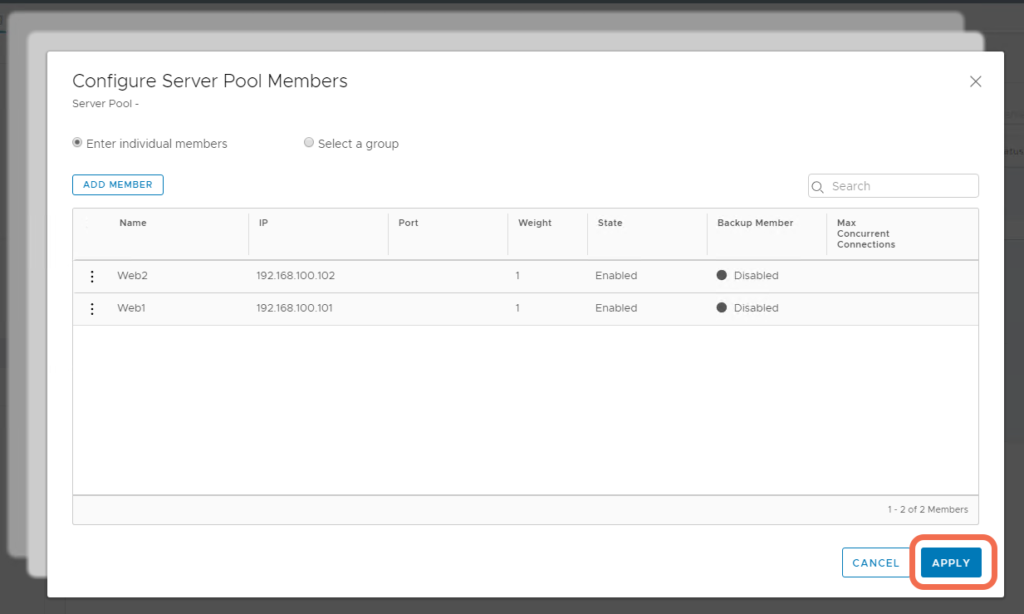
Step 9: Verify that the Load Balancer, Virtual Server, and Server Pool appear Up and healthy
With the implementation complete, verify all Load Balancer components appear up and healthy:


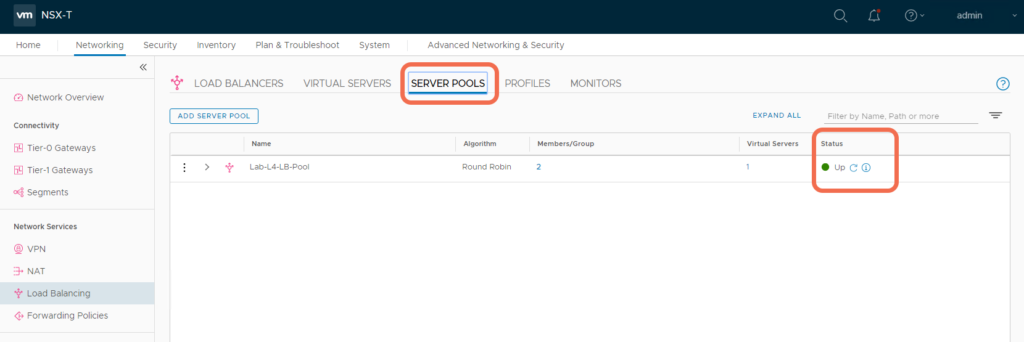
Step 10: Verify Load Balancer Operation
With this setup, the Service Interface, VIP, and Pool Members are all reachable.
C:\Users\Administrator> ping 192.168.100.101          <--- Pool Memeber Web1


Pinging 192.168.100.101 with 32 bytes of data:
Reply from 192.168.100.101: bytes=32 time=3ms TTL=63
Reply from 192.168.100.101: bytes=32 time=5ms TTL=63
Reply from 192.168.100.101: bytes=32 time=2ms TTL=63
Reply from 192.168.100.101: bytes=32 time=2ms TTL=63


Ping statistics for 192.168.100.101:
    Packets: Sent = 4, Received = 4, Lost = 0 (0% loss),
Approximate round trip times in milli-seconds:
    Minimum = 2ms, Maximum = 5ms, Average = 3ms


C:\Users\Administrator> ping 192.168.100.102          <--- Pool Memeber Web2


Pinging 192.168.100.102 with 32 bytes of data:
Reply from 192.168.100.102: bytes=32 time=2ms TTL=63
Reply from 192.168.100.102: bytes=32 time=7ms TTL=63
Reply from 192.168.100.102: bytes=32 time=1ms TTL=63
Reply from 192.168.100.102: bytes=32 time=4ms TTL=63


Ping statistics for 192.168.100.102:
    Packets: Sent = 4, Received = 4, Lost = 0 (0% loss),
Approximate round trip times in milli-seconds:
    Minimum = 1ms, Maximum = 7ms, Average = 3ms


C:\Users\Administrator> ping 192.168.100.60          <--- VIP


Pinging 192.168.100.60 with 32 bytes of data:
Reply from 192.168.100.60: bytes=32 time=6ms TTL=63
Reply from 192.168.100.60: bytes=32 time=2ms TTL=63
Reply from 192.168.100.60: bytes=32 time=3ms TTL=63
Reply from 192.168.100.60: bytes=32 time=2ms TTL=63


Ping statistics for 192.168.100.60:
    Packets: Sent = 4, Received = 4, Lost = 0 (0% loss),
Approximate round trip times in milli-seconds:
    Minimum = 2ms, Maximum = 6ms, Average = 3ms


C:\Users\Administrator> ping 192.168.100.50          <--- Service Interafce


Pinging 192.168.100.50 with 32 bytes of data:
Reply from 192.168.100.50: bytes=32 time=2ms TTL=63
Reply from 192.168.100.50: bytes=32 time=2ms TTL=63
Reply from 192.168.100.50: bytes=32 time=2ms TTL=63
Reply from 192.168.100.50: bytes=32 time=5ms TTL=63


Ping statistics for 192.168.100.50:
    Packets: Sent = 4, Received = 4, Lost = 0 (0% loss),
Approximate round trip times in milli-seconds:
    Minimum = 2ms, Maximum = 5ms, Average = 2ms
With this setup, both pool members are running an Apache HTTP Service on Photon OS, and are accessible from physical.


The Load Balancer VIP is accessible from physical.

Reviewing the Load Balancer Configuration from the NSX-T Edge CLI
nsxtedge01(tier1_sr)> get high-availability status
Service Router
UUID : 4bdc9e60-1952-4981-8214-9ebd8fcfdb95
state : Active                                                 <--- Be sure to view the status from the Active Edge
.....

nsxtedge01> get logical-router
Logical Router
UUID VRF LR-ID Name Type Ports
736a80e3-23f6-5a2d-81d6-bbefb2786666 0 0 TUNNEL 3
4bdc9e60-1952-4981-8214-9ebd8fcfdb95 2 12 SR-Lab-LB SERVICE_ROUTER_TIER1 5 . <--- VRF 2 is Tier-1 Gateway SR-Lab-LB

nsxtedge01> vrf 2

nsxtedge01(tier1_sr)> get int | find Name|state|IP|MAC|VNI|Interface
UUID VRF LR-ID Name Type
Interfaces (IPv6 DAD Status A-Assigned, D-Duplicate, T-Tentative)
Interface : fca7c715-41d2-477d-a78a-d522d78874a4
Name : t1-Lab-LB-71df9d00-86ee-11ea-b9
IP/Mask : 192.168.100.50/24                                    <--- Service Interface
MAC : 00:50:56:96:6e:f9
Op_state : up                                                  <--- Service Interface is up
Interface : 134041c9-a7dc-4c11-897b-544882e7c7be
Name : bp-sr0-port
IP/Mask : 169.254.0.2/28;fe80::50:56ff:fe56:5300/64(NA)        <--- VIP
MAC : 02:50:56:56:53:00
Op_state : up                                                  <--- VIP is up
Interface : 8dec9e30-5376-4359-b4bb-dbd464eb9a42
IP/Mask : 127.0.0.1/8;192.168.100.60/32;::1/128(NA)
Interface : cbf10d31-8abc-5366-9f7a-790f9a29a378
Interface : 149f410c-5c9e-5278-8c0b-92d10c2269ea

nsxtedge01(tier1_sr)> exit

nsxtedge01> get load-balancer
Load Balancer
Access Log Enabled : False
Display Name : Lab-L4-LB
Enabled : True
UUID : fa341b38-125e-41e9-8323-136f52eaaad5                    <--- Losd Balancer UUID
Log Level : LB_LOG_LEVEL_INFO
Size : SMALL
Virtual Server Id : 3973707b-782b-4245-910b-633bde6193f2

nsxtedge01> get load-balancer fa341b38-125e-41e9-8323-136f52eaaad5 virtual-server status
Virtual Server
UUID : 3973707b-782b-4245-910b-633bde6193f2
Display-Name: Lab-L4-LB-VIP
IP : 192.168.100.60
Port : 80
Status : up

nsxtedge01> get load-balancer fa341b38-125e-41e9-8323-136f52eaaad5 virtual-server stats
Virtual Server
UUID : 3973707b-782b-4245-910b-633bde6193f2
Display-Name : Lab-L4-LB-VIP
VIP : TCP 192.168.100.60:80
Type : L4
Sessions :
(Cur, Max, Total, Rate) : (0, 1, 3, 0)
Bytes :
(In, Out) : (2890, 1473)
Packets :
(In, Out) : (19, 17)


nsxtedge01> get load-balancer fa341b38-125e-41e9-8323-136f52eaaad5 pools
Pool
Active Monitor Id : f3dfe85c-dbfa-475b-930e-cb900776fc8b
Algorithm : ROUND_ROBIN
Display Name : Lab-L4-LB-Pool
UUID : 14303018-f52b-4a59-bdd4-a5811d8e99bf
Member :
Admin State : ENABLED
Backup Member : False
Display Name : Web2
Ip Address :
Ipv4 : 192.168.100.102
Weight : 1
Admin State : ENABLED Backup Member : False Display Name : Web1 Ip Address : Ipv4 : 192.168.100.101 Weight : 1
Min Active Members : 1
Snat Translation :
Auto Map : True
Port Overload : 32
Tcp Multiplexing Enabled : False
Tcp Multiplexing Number : 6
I hope this simple topology for a Standalone VLAN Based OneArm Load Balancer helps in providing a base configuration from which you can build more complex scenarios,

