Troubleshooting BGP Peering on NSX-T Edges
Introduction:
In this article, we will look at a troubleshooting approach for network connectivity issues, known as the Bottom-Up Methodology. We will take a close look at troubleshooting BGP Peer Establishment on NSX-T edges to illustrate this approach.
- Bottom-Up is a structured approach often used in troubleshooting network communication issues
- Troubleshooting starts from the Open Systems Interconnection model (OSI model) physical layer and moves up towards the application layer
- This systematically eliminates potential problems at lower levels narrowing the scope as troubleshooting progresses
- This approach is well suited to troubleshooting the Border Gateway Protocol (BGP)
Physical Layer Troubleshooting, troubleshooting the transfer of bits
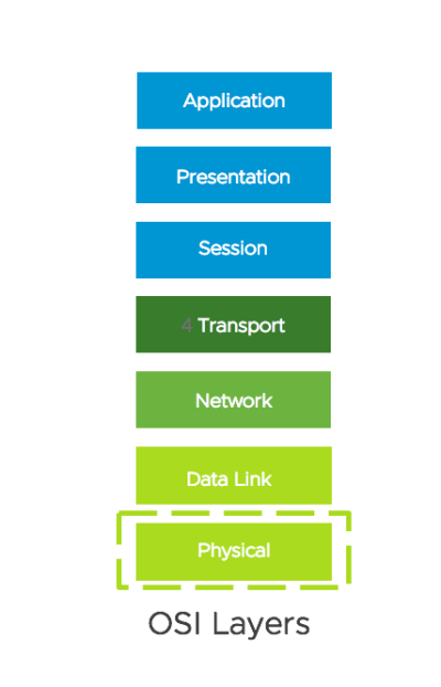
- In traditional networks, the physical layer defines the means of transmitting raw bits over a physical data link connecting network nodes.
- In an NSX-T environment, we will extend the physical network view to include a logical topology and virtualized components.
- This stage of troubleshooting will include mapping out of physical and virtualized components such as routers, switches, segments, interfaces, hosts, and edges.
Physical Layer Troubleshooting, sample topology for BGP Peers
We have created a logical topology with virtualized and physical components as a reference for troubleshooting BGP peering on NSX-T Edges.
In this logical topology four interfaces have been identified for the interconnection of the physical router to the Tier-0 Service Router (SR).
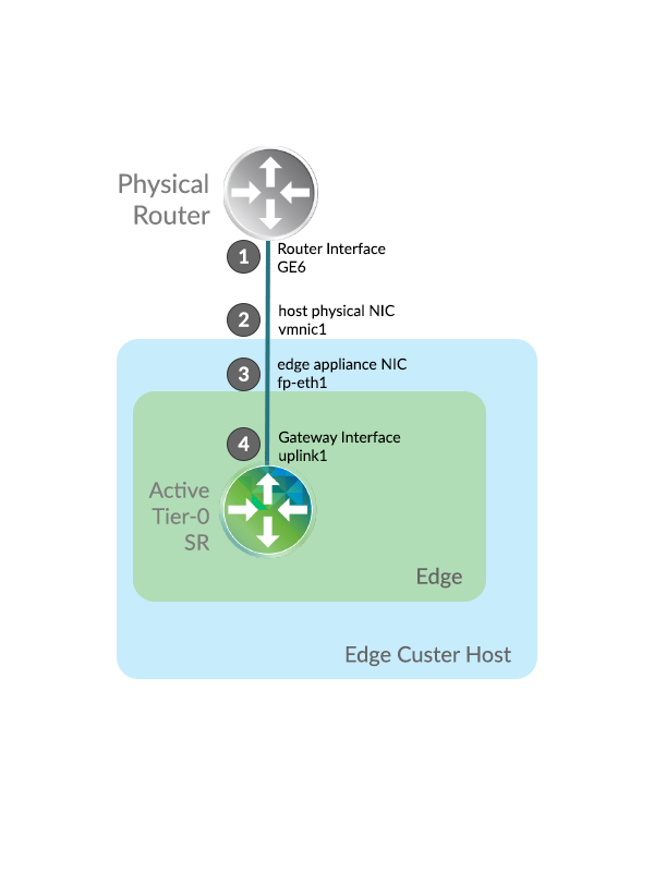
Physical Layer Troubleshooting, working Scenario: All interfaces are up
Interface1, Router Interface GE6:
PhysicalRouter# show ip interface brief
Interface              IP-Address      OK? Method Status                Protocol
GigabitEthernet1       192.168.21.2    YES NVRAM  up                    up
GigabitEthernet2       10.155.14.10    YES NVRAM  up                    up
GigabitEthernet3       192.168.110.2   YES NVRAM  up                    up
GigabitEthernet4       10.160.110.2    YES NVRAM  up                    up
GigabitEthernet5       1.1.1.1         YES NVRAM  down                  down
GigabitEthernet6       192.168.100.2   YES NVRAM  up                    up
GigabitEthernet7       192.168.150.2   YES NVRAM  up                    up
GigabitEthernet8       unassigned      YES NVRAM  administratively down down
GigabitEthernet9       unassigned      YES NVRAM  administratively down down
GigabitEthernet10      unassigned      YES NVRAM  administratively down down
Loopback0              unassigned      YES unset  up                    up

Interface2, host physical NIC vmnic1:
[root@esx03-s1:~] esxcli network nic list
Name    PCI Device    Driver  Admin Status  Link Status  Speed  Duplex  MAC Address         MTU  Description
------  ------------  ------  ------------  -----------  -----  ------  -----------------  ----  --------------------------------------------------------------
vmnic0  0000:02:00.0  e1000   Up            Up            1000  Full    00:50:56:01:48:99  1600  Intel Corporation 82545EM Gigabit Ethernet
vmnic1  0000:02:01.0  e1000   Up            Up            1000  Full    00:50:56:01:48:9a  1600  Intel Corporation 82545EM Gigabit Ethernet
vmnic2  0000:02:02.0  e1000   Up            Up            1000  Full    00:50:56:01:48:9b  1600  Intel Corporation 82545EM Gigabit Ethernet
vmnic3  0000:02:03.0  e1000   Up            Up            1000  Full    00:50:56:01:48:9c  1600  Intel Corporation 82545EM Gigabit Ethernet

Interface3, edge appliance NIC fp-eth1:
nsxtedge01> get int fp-eth1
Interface: fp-eth1
  ID: 1
  Link status: up
  MAC address: 00:50:56:96:6e:f9

Interface4, Gateway Interface uplink1:
nsxtedge01(tier0_sr)> get interfaces
...
Interface     : 99162a40-21cc-4dea-b1da-2011df476041
    Ifuid         : 321
    Name          : ulink1
    Internal name : uplink-321
    Mode          : lif
    IP/Mask       : 192.168.100.102/24
    MAC           : 00:50:56:96:6e:f9
    LS port       : 681b9c8c-aa1d-45b0-8cf6-7bfc95af9d9a
    Urpf-mode     : STRICT_MODE
    DAD-mode      : LOOSE
    RA-mode       : SLAAC_DNS_TRHOUGH_RA(M=0, O=0)
    Admin         : up
    Op_state      : up
    MTU           : 1500
All Interfaces are up. We have successfully verified that devices along the path are powered, that interface configurations have been realized, and that interfaces are physically and administratively up. Physical Layer operation has been validated
Data Link Layer Troubleshooting, troubleshooting the transfer of data frames
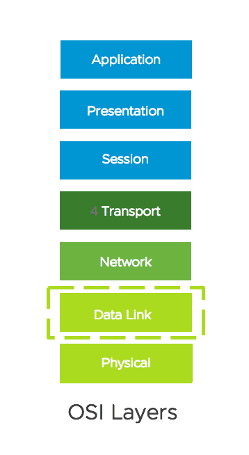
- A media access control address (MAC address) is a unique identifier assigned to a network interface controller (NIC) known at the Data Link Layer.
- The Address Resolution Protocol (ARP) is a communication protocol used for discovering the link-layer address, such as a MAC address.
- We will be troubleshooting the ability of communication endpoints to learn each other’s MAC address via ARP.
Notice that MAC addresses have been correctly learned:

PhysicalRouter# show arp GigabitEthernet6
Protocol  Address          Age (min)  Hardware Addr   Type   Interface
Internet  192.168.100.2           -   0050.5601.3cbc  ARPA   GigabitEthernet6
Internet  192.168.100.103         0   0050.5696.fb51  ARPA   GigabitEthernet6
Internet  192.168.100.102         0   0050.5696.6ef9  ARPA   GigabitEthernet6


nsxtedge01> get int fp-eth1
Interface: fp-eth1
  ID: 1
  Link status: up
  MAC address: 00:50:56:96:6e:f9


nsxtedge01(tier0_sr)> get neighbor
Logical Router
UUID        : 0d5bfdc7-3df9-4b21-b83d-8d7c350fb983
VRF         : 5
LR-ID       : 1026
Name        : SR-lab-tier-0
Type        : SERVICE_ROUTER_TIER0
Neighbor
    Interface   : 99162a40-21cc-4dea-b1da-2011df476041
    IP          : 192.168.100.2
    MAC         : 00:50:56:01:3c:bc
    State       : reach
    Timeout     : 600

PhysicalRouter #show int gigabitEthernet6
GigabitEthernet6 is up, line protocol is up
  Hardware is CSR vNIC, address is 0050.5601.3cbc (bia 0050.5601.3cbc)
  Description: Site01_EdgeNetworks-1
  Internet address is 192.168.100.2/24
MAC addresses have been correctly learned by both endpoints. Data Link Layer operation has been validated.
Perform traffic captures along the data path, in this case location 2:
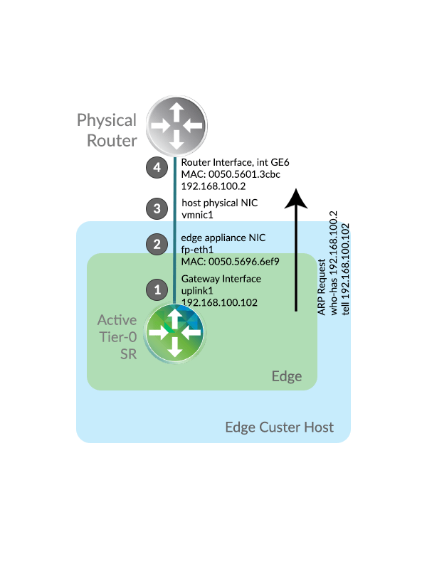
nsxtedge01> start capture interface fp-eth1 expression arp

20:22:08.098654 00:50:56:96:6e:f9 > 00:50:56:01:3c:bc, ethertype 802.1Q (0x8100), length 64: vlan 0, p 0, ethertype ARP, Request who-has 192.168.100.2 tell 192.168.100.102, length 46
<base64>AFBWATy8AFBWlm75gQAAAAgGAAEIAAYEAAEAUFaWbvnAqGRmAAAAAAAAwKhkAgAAAAAAAAAAAAAAAAAAAAAAAA==</base64>

20:22:08.103883 00:50:56:01:3c:bc > 00:50:56:96:6e:f9, ethertype ARP (0x0806), length 60: Reply 192.168.100.2 is-at 00:50:56:01:3c:bc, length 46
<base64>AFBWlm75AFBWATy8CAYAAQgABgQAAgBQVgE8vMCoZAIAUFaWbvnAqGRmAAAAAAAAAAAAAAAAAAAAAAAA</base64>
This is a rigorous method in troubleshooting MAC Learning.
Network Layer Troubleshooting, troubleshooting the transfer of packets
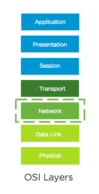
- This layer determines how data is sent to the receiving device. It’s responsible for packet forwarding, routing, and addressing.
- The Internet Protocol (IP) operates on this layer. •Each node is identified by one or more unique IP addresses.
- Ping can be used to test the Network Layer.
Network Layer Troubleshooting, working scenario
Here we will ping the physical router IP address from within the Tier-0 SR Virtual routing and forwarding (VRF) instance, specifying the source IP address as the Gateway interface:
nsxtedge01> vrf 3
nsxtedge01(tier0_sr)> ping 192.168.100.2 source 192.168.100.102
PING 192.168.100.2 (192.168.100.2) from 192.168.100.102: 56 data bytes
64 bytes from 192.168.100.2: icmp_seq=0 ttl=255 time=13.430 ms
64 bytes from 192.168.100.2: icmp_seq=1 ttl=255 time=2.054 ms
64 bytes from 192.168.100.2: icmp_seq=2 ttl=255 time=2.629 ms

Remember to specify the source IP address as the Gateway interface to get full control over the ping request.
Network Layer Troubleshooting, routing occurs at the Network Layer
By design the Edge will not route unless this underlying requirement is met:
- The inclusion of an Overlay Transport Zone on the edge node.
- The edge node has at least one Termination End Point (TEP) interface.
- At least one active Bidirectional Forwarding Detection (BFD) GENEVE tunnel to the edge
This failsafe helps prevent traffic flow over failed paths.
Network Layer Troubleshooting, Validating Base Routing Requirements
This example illustrates the close relationship between TEP reachability and routing status. Routing is currently down since remote TEPs are unreachable. Base routing requirements are not met:
nsxtedge01> get edge-cluster status
High Availability State     : Inactive
                  Since     : 2020-08-01 09:40:59.43
Edge Node Id                : 7af45036-6d42-11ea-a22d-00505696b642
Edge Node Status            : Down
Admin State                 : Up
Vtep State                  : Up
Configuration               : applied
Health Check Config         :
    Interval                : 1000 msec
    Deadtime                : 3000 msec
    Max Hops                : 255
Service Status              :
    Datapath Config Channel : Up
    Datapath Status Channel : Up
    Routing Status Channel  : Up
    Routing Status          : Down     <----
Peer Status                 :
    Node Id                 : d3937794-6d42-11ea-8ce8-0050569629d4
    Node Thumbprint         : C0:BB:C2:44:11:A1:CB:36:15:55:FF...
    Node Status             : Up
    Healthcheck Sessions    :
        Interface           : eth0
        Session             : 192.168.110.65:192.168.110.66
        Status              : Up

        Interface           : nsx-edge-vtep. <---- TEP interface
        Device              : fp-eth2
        Session             : 192.168.110.181:192.168.110.186
        Status              : Unreachable    <----
Transport Layer Troubleshooting, troubleshooting the transfer of segments
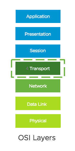
- This layer provides the functional and procedural means of transferring variable-length data sequences from a source to a destination host while maintaining the quality of service functions.
- The Transmission Control Protocol (TCP) and the User Datagram Protocol (UDP) operate on this layer.
- BGP uses TCP port 179 to communicate between routers.
- Although BGP is a routing protocol for the purpose of this guide we will place BGP troubleshooting at the Transport layer since peer establishment is TCP session based.
Sample BGP Network Topology, BGP Topology for this Guide
In NSX-T BGP peers interconnect physical and virtualized environments. In this topology:
- The Virtual environment needs to learn the quad-zero route 0.0.0.0/0 to Physical.
- The Physical environment needs to learn the workload segment route 192.168.70.0/24.
- These routes are to be exchanged between established BGP Peers.
This is a similar topology we looked at here: https://spillthensxt.com/base-bgp-configuration-in-nsx-t/
Transport Layer Troubleshooting, identifying the Tier-0 Service Router
There are multiple Virtual Routing and Forwarding (VRF) instances within the Edge gateway:

nsxtedge01> get logical-router
Logical Router
UUID                                   VRF    LR-ID  Name            Type                        Ports
736a80e3-23f6-5a2d-81d6-bbefb2786666   0      0                      TUNNEL                      3
d4eb470c-06f2-47ad-92ce-469e6815e7b3   1      1029   DR-lab-tier-1   DISTRIBUTED_ROUTER_TIER1    6
c66689af-13c3-4745-ba01-84f308b39bc5   2      1025   DR-lab-tier-0   DISTRIBUTED_ROUTER_TIER0    4
0d5bfdc7-3df9-4b21-b83d-8d7c350fb983   3      1026   SR-lab-tier-0   SERVICE_ROUTER_TIER0        5

Our focus is on Tier-0 Service Router, in this case VRF 3, which handles BGP routing to physical.

nsxtedge01> vrf 3
nsxtedge01(tier0_sr)>
Transport Layer Troubleshooting, verifying BGP State
The BGP neighbor summary is a convenient way to determine the BGP state for each peer-to-peer session:
nsxtedge01(tier0_sr)> get bgp neighbor summary
BFD States: NC - Not configured, AC - Activating,DC - Disconnected
            AD - Admin down, DW - Down, IN - Init,UP - Up
BGP summary information for VRF default for address-family: ipv4Unicast
Router ID: 192.168.100.102  Local AS: 65111

Neighbor                            AS          State Up/DownTime  BFD InMsgs  OutMsgs InPfx  OutPfx
192.168.100.2                       65100       Estab 00:18:31     NC  24      25      1      3

BGP peers have one of six states: Idle; Connect; Active; OpenSent; OpenConfirm; and Established.

The goal is to have BGP peers reach the Established state, where routes are exchanged.
Transport Layer Troubleshooting, viewing the BGP Table
View the contents of the BGP table:
nsxtedge01(tier0_sr)> get bgp
BGP table version is 3, local router ID is 192.168.100.102
Status flags: > - best, I - internal
Origin flags: i - IGP, e - EGP, ? - incomplete

   Network              Next Hop             Metric       LocPrf  Weight     Path
 > 0.0.0.0/0            192.168.100.2        0            100     0         65100 65111 i
 > 192.168.70.0/24      100.64.192.1         0            100     32768     65111   ?
 > 192.168.100.0/24     0.0.0.0              0            100     32768     65111   ?

The BGP Table routes do not have the outgoing interface, only next hop and attributes used in path selection.
Transport Layer Troubleshooting, viewing the Routing Table
View the contents of the route table:
nsxtedge01(tier0_sr)> get route
Flags: t0c - Tier0-Connected, t0s - Tier0-Static, B - BGP,
t0n - Tier0-NAT, t1s - Tier1-Static, t1c - Tier1-Connected,
t1n: Tier1-NAT, t1l: Tier1-LB VIP, t1ls: Tier1-LB SNAT,
t1d: Tier1-DNS FORWARDER, t1ipsec: Tier1-IPSec,
> - selected route, * - FIB route
Total number of routes: 6

b  > * 0.0.0.0/0 [20/0] via 192.168.100.2, uplink-276, 05:53:14
t0c> * 100.64.192.0/31 is directly connected, linked-277, 05:53:15
t1c> * 192.168.70.0/24 [3/0] via 100.64.192.1, linked-277, 05:53:12
t0c> * 192.168.100.0/24 is directly connected, uplink-276, 05:53:15
t0c> * fcd2:ed7a:395c:8000::/64 is directly connected, linked-277, 05:53:15
t0c> * fe80::/64 is directly connected, linked-277, 05:53:15

The Route Table contains routes from multiple sources such as connected, static, and BGP, and the outgoing interface for each route.
Transport Layer Troubleshooting, viewing the Forwarding Table
View the contents of the forwarding table:
nsxtedge01(tier0_sr)> get forwarding
Logical Router
UUID                                   VRF    LR-ID  Name                   Type
0d5bfdc7-3df9-4b21-b83d-8d7c350fb983   3      1026   SR-lab-tier-0          SERVICE_ROUTER_TIER0
IPv4 Forwarding Table
IP Prefix          Gateway IP      Type     UUID
0.0.0.0/0          192.168.100.2   route    99162a40-21cc-4dea-b1da-2011df476041
100.64.192.0/32                    route    58af35d2-c92e-5350-9563-4ee4171fdacf
100.64.192.0/31                    route    95f7ce5a-4166-4a2f-9689-13602fd5cdfe
127.0.0.1/32                       route    5dfdebf2-9a50-4477-aba5-1a1d17594618
169.254.0.0/28                     route    e4723931-8549-4bda-9fd7-8ee09108745f
169.254.0.1/32                     route    58af35d2-c92e-5350-9563-4ee4171fdacf
169.254.0.2/32                     route    863701c2-bf07-5b64-88ca-dcfdff6e73a0
192.168.70.0/24    100.64.192.1    route    95f7ce5a-4166-4a2f-9689-13602fd5cdfe
192.168.100.0/24                   route    99162a40-21cc-4dea-b1da-2011df476041
192.168.100.102/32

The forwarding table contains only the routes which are chosen by the routing algorithm as preferred routes for packet forwarding.
Transport Layer Troubleshooting, viewing Advertised Routes
View routes being advertised to a BGP peer:
nsxtedge01(tier0_sr)> get bgp neighbor 192.168.100.2 advertised-routes

BGP table version is 3, local router ID is 192.168.100.102
Status flags: > - best, I - internal
Origin flags: i - IGP, e - EGP, ? - incomplete

   Network              Next Hop                            Metric       LocPrf   Weight  Path
 > 0.0.0.0/0            192.168.100.2                       0            100        0     65100    i
 > 192.168.70.0/24      0.0.0.0                             0            100      32768            ?
 > 192.168.100.0/24     0.0.0.0                             0            100      32768            ?

The workload routes are being advertised to the physical router.
Transport Layer Troubleshooting, troubleshooting BGP peer establishment with debug BGP
BGP debugging can be enabled within the Tier-0 SR:
nsxtedge01(tier0_sr)> set debug bgp
BGP updates debugging is on
BGP keepalives debugging is on
BGP neighbor-events debugging is on

nsxtedge01(tier0_sr)> get debug bgp
2020/08/05 12:48:32.056189 BGP: eor_required 0, eor_received 0
2020/08/05 12:48:32.056213 BGP: rcvd End-of-RIB for IPv4 Unicast from 192.168.100.2
2020/08/05 12:48:32.116421 ZEBRA: skip installing routes into kernel.
2020/08/05 12:48:33.044257 BGP: 192.168.100.2 [FSM] Timer (routeadv timer expire)
2020/08/05 12:48:33.627188 ZEBRA: skip installing routes into kernel.
2020/08/05 19:40:32.144221 BGP: 192.168.100.2 [FSM] Timer (keepalive timer expire)
2020/08/05 19:40:32.144845 BGP: 192.168.100.2 sending KEEPALIVE
2020/08/05 19:40:54.360006 BGP: 192.168.100.2 KEEPALIVE rcvd
2020/08/05 19:41:32.144388 BGP: 192.168.100.2 [FSM] Timer (keepalive timer expire)
2020/08/05 19:41:32.144514 BGP: 192.168.100.2 sending KEEPALIVE

nsxtedge01(tier0_sr)> clear debug bgp
BGP updates debugging is off
BGP keepalives debugging is off
BGP neighbor-events debugging is off

This is an excellent method in troubleshooting BGP peer establishment.
Transport Layer Troubleshooting, troubleshooting BGP peer establishment with packet captures
A packet capture can be run on the Tier-0 SR uplink interface:
nsxtedge01(tier0_sr)> get int | find Name|IP|MAC|Interface
    Interface     : e4723931-8549-4bda-9fd7-8ee09108745f
    Name          : bp-sr0-port
    IP/Mask       : 169.254.0.2/28;fe80::50:56ff:fe56:5300/64(NA)
    MAC           : 02:50:56:56:53:00
    Interface     : 99162a40-21cc-4dea-b1da-2011df476041  ß the interface UUID of interest
    Name          : ulink1
    IP/Mask       : 192.168.100.102/24
    MAC           : 00:50:56:96:6e:f9

nsxtedge01(tier0_sr)> exit
nsxtedge01> start capture interface 99162a40-21cc-4dea-b1da-2011df476041 expression tcp port 179

22:02:32.319243 00:50:56:96:6e:f9 > 00:50:56:01:3c:bc, ethertype 802.1Q (0x8100), length 77: vlan 0, p 0, ethertype IPv4, 192.168.100.102.34953 > 192.168.100.2.179: Flags [P.], seq 568758399:568758418, ack 1408489092, win 29200, length 19: BGP
<base64>AFBWATy8AFBWlm75gQAAAAgARcAAOw2RQAABBiGzwKhkZsCoZAKIiQCzIeaQf1Pz1oRQGHIQicIAAP////////////////////8AEwQ=</base64>

22:02:32.520365 00:50:56:01:3c:bc > 00:50:56:96:6e:f9, ethertype IPv4 (0x0800), length 60: 192.168.100.2.179 > 192.168.100.102.34953: Flags [.], ack 19, win 15719, length 0
<base64>AFBWlm75AFBWATy8CABFwAAorGxAAAEGgurAqGQCwKhkZgCziIlT89aEIeaQklAQPWfChgAAAAAAAAAA</base64>

This is a more complex method in troubleshooting BGP peer establishment.
Transport Layer Troubleshooting, troubleshooting BGP peer establishment with packet captures for offline analysis
A packet capture can be run on the Tier-0 SR uplink interface:
nsxtedge01> start capture interface 99162a40-21cc-4dea-b1da-2011df476041 file edge01.pcap expression tcp port 179

Capture to file initiated, enter Ctrl-C to terminate

6 packets captured
6 packets received by filter
0 packets dropped by kernel

The file edge01.pcap can be examined closely offline with a packet analyzer such as Wireshark for detailed analysis.
BGP Troubleshooting Summary, a review of Objectives and Commands at each Layer
Here are a list of commands used in troubleshooting BGP peering on NSX-T Edges
BGP Troubleshooting Summary, Commands at each Layer
Physical Layer:
nsxtedge01(tier0_sr)> get interfaces

Data Link Layer:
nsxtedge01(tier0_sr)> get neighbor
nsxtedge01> start capture interface <int> expression arp

Network Layer:
nsxtedge01(tier0_sr)> ping <dst-ip> source <src-ip>
nsxtedge01> get edge-cluster status

Transport Layer:
nsxtedge01(tier0_sr)> get bgp neighbor summary
nsxtedge01(tier0_sr)> get bgp
nsxtedge01(tier0_sr)> get route
nsxtedge01(tier0_sr)> get forwarding
nsxtedge01(tier0_sr)> get bgp neighbor <nei-ip> advertised-routes
nsxtedge01(tier0_sr)> set debug bgp
nsxtedge01(tier0_sr)> get debug bgp
nsxtedge01> start capture interface <int> expression tcp port 179
Troubleshooting Scenario putting what you learned into practice
You have been asked to help troubleshoot a new NSX-T Edge Installation, where BGP Peers will not come up
The NSX-T Administrator has advised that the Edge can ping the physical BGP peer, and strongly suspects that the issue is a mismatched BGP configuration.

The NSX-T Administrator has provided the following commands output for your review:
root@nsxtedge01:~# ping 192.168.100.2
PING 192.168.100.2 (192.168.100.2) 56(84) bytes of data.
64 bytes from 192.168.100.2: icmp_seq=1 ttl=255 time=1.48 ms
64 bytes from 192.168.100.2: icmp_seq=2 ttl=255 time=0.956 ms
64 bytes from 192.168.100.2: icmp_seq=3 ttl=255 time=1.11 ms
64 bytes from 192.168.100.2: icmp_seq=4 ttl=255 time=0.992 ms
Question: What has the NSX-T Administrator demonstrated? (hint, how confident can you be on the source IP address of the ping)
Question: What OSI Layer would be your next step in troubleshooting and why?
Question: Where would you look to rule out a duplicate IP?




Thank you for your great work.. would u please post NSX-t logs file locations
Thanks
Basem
Thank you Basem!
On NSX-T Edges, when logged in as root, you will find logs in /var/log, with the best details often in /var/log/syslog
Best Regards,
Gary